Machining NeoNickel High Performance Alloys
Alloy Categories
- Machinability for Duplex/Super Duplex, Austenitic stainless grades, precipitation hardened stainless grades, Titanium and Cobalt Alloys
- Machining Nickel Alloys
- Machining Titanium Alloys
The machining of high performance alloys can be readily accomplished providing fundamental principles affecting the machinability are understood and taken into consideration.
Key points:
High performance alloys are much stronger than plain carbon steels. For example, Nickel Alloys are usually much stronger at metal cutting temperatures and they are “gummy” with chips that tend to be stringy and tough.
It is crucial to understand the basic properties of the materials being machined. Tooling which is the optimum choice for material in the annealed condition will not be the same as when the material is the aged / precipitation hardened condition.
Reducing effect of work hardening in the material by minimising cold working / polishing the surface of the material. The avoidance of work hardening is of key to the successful machining of Nickel Alloys. Work hardening occurs when the metal ahead of the cutting tool, especially one that is cutting poorly, is plastically deformed. This hardened layer is very difficult to penetrate in subsequent passes or operations. Techniques which minimise the effect of work hardening include the use of sharp cutting edges, positive rake angles, adequate clearance angles, avoidance of dwelling and machines set ups have sufficient power and rigidity to keep vibration to a minimum. Moreover, feed rate and cutting depth should be set so that in following passes cutting is done below the previously work hardened layer. Vibration can be minimised by using the largest possible tools and tool holders and by limiting overhang. Finally, power requirements should be determined based on the machine using 50% of the machines capacity.
High torque, powerful, rigid machines provide the best result when machining high performance alloys. Both the tool and the work piece should be held rigid. Rigidity is particularly important when machining titanium as titanium has a much lower modulus of elasticity than steels, stainless steels and Nickel Alloys.
Tooling should be selected to minimize cutting forces, maximum edge strength and have the ability to withstand the highest cutting temperatures. Tooling should always be sharp by changing to sharpened tools at regular intervals. Titanium Chips in particular tend to gall and weld to tooling cutting edges, speeding up tool wear and premature failure. (NB: Cutting edges – inserts are relatively low cost and expendable.)
Utilising correct coolants /lubricants is also very important in machining high performance alloys. Sulphur chlorinated petroleum oil lubricants are suggested for all alloys with the exception of Titanium. Lubricants or cutting fluids for Titanium should not contain chlorine or other halogens i.e. fluorine, bromine or iodine in order to reduce the risk of corrosion issues. When machining Nickel Alloys the choice of cutting fluid is dependant on whether cooling or lubrication is the primary requirement. In low speed cutting with high speed steel tools (HSS tools) a sulphur chlorinated oil that has the viscosity adjusted to the operation is preferred. Normally a high viscosity lubricant will offer optimum tool life while a lighter viscosity lubricant will aid in chip flushing in small deep holes. When using oil, the high cutting temperatures generated may produce a brown sulphur stain on the surface of the material. This stain is easily removed by the use of sodium cyanide or chromic – sulphuric acid cleaning solutions. Soluble water based coolants are preferred when used in high metal removal where heat removal is essential. (NB: It is critical that sulphur stain is removed prior to subsequent heating or welding as the sulphur contamination can lead to intergranular corrosion attack)
Machinability for Duplex/Super Duplex, Austenitic stainless grades, precipitation hardened stainless grades, Titanium and Cobalt Alloys
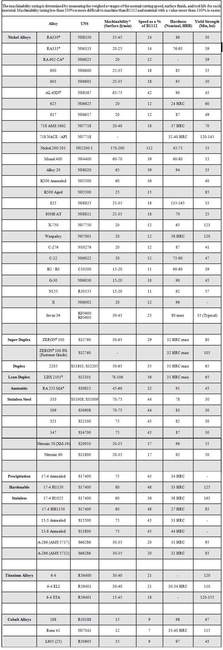
Machinability chart (machining speeds) for Nickel Alloys, Duplex/Super Duplex, Austenitic Stainless grades, precipitation hardened stainless grades, Titanium Alloys and Cobalt alloys stocked by NeoNickel
The following speeds are for single point turning operations using high speed tools. This information is provided as a guide to relative machinability, higher speeds are used with carbide tooling.
The machinability rating quantifies the machinability of various materials. The American Iron and Steel Institute (AISI) determined machinability ratings for a wide variety of materials by running turning tests at 180 surface feet per minute (sfpm) and arbitrarily assigned 160 Brinell B112 steel a machineability rating of 100%.
Machining Nickel Alloys
Nickel Alloys and machinability reference
| Group | Group Characteristics | Alloy | UNS No | Werkstoff / DIN No | Alloy Type |
|---|---|---|---|---|---|
| A | ‘Gummy’ behaviour in annealed condition
Hardenable only by cold working (best condition for machining | 200
201 | N02200
N02201 | 2.4066
2.4068 | Pure Nickel
Pure Nickel |
| B | Higher strength work hardened than Group A alloys
Mostly not Hardenable Best machining in cold-drawn or cold-drawn and stress-relieved conditions | 400
36 | NO4400
K93603 | 2.4360
1.3912 | Nickel Copper
Nickel Iron |
| C | Similar mechanical properties to austenitic stainless steels accept for greater high temperature strength
Best machining in cold-drawn or cold-drawn and stress-relieved conditions | 600
601 690 825 RA330 20 800 800H 800HT K500 Un-aged 75 86 | N06600
N06601 N06690 N08825 N08330 N08020 N08800 N08810 N08811 N05500 N06075 | 2.4816
2.4851 2.4642 2.4858 1.4886 2.4660 1.4876 1.4958 1.4959 2.4375 2.4951 | Nickel Chromium
Nickel Chromium High Chromium Nickel Al Nickel Iron Chromium Nickel Iron Chromium Nickel Iron Chromium + Copper & Molybdenum Nickel Iron Chromium Nickel Iron Chromium Nickel Iron Chromium Nickel Copper Nickel Chromium Nickel Chromium |
| D1 | Aged-hardened alloys in the solution annealed condition
Relatively easy to machine | 925 Annealed | N09925 | Nickel Iron Chromium | |
| D2 | Aged-hardenable alloys in both solution-annealed and hardened condition. Some contain strong solution strengtheners and hard abrasive precipitates Difficult to machine Rough machine in annealed condition and then finish machined after aging
NB: 0.07% size contraction after aging (should be allowed for during rough machining) | K500 Aged
X 625 925 Aged 725 80A 718 PE 11 PE 16 C276 22 X750 617 C263 105 90 115 B2 B3 230 602CA | N05500
N06002 N06625 N09925 N07725 N07080 N07718 N10276 N06022 N07750 N06617 N07263 N07090 N10665 N10675 N06230 N06025 | 2.4375
2.4665 2.4856 2.4952 2.4668 2.4819 2.4602 2.4669 2.4663 2.4650 2.4634 2.4636 2.4617 2.4600 2.4733 2.4633 | PH Nickel Copper
Nickel Chromium Iron Molybdenum Nickel Chromium Molybdenum Niobium PH Nickel Iron Chromium PH Nickel Chromium Molybdenum Niobium Nickel Chromium PH Nickel Chromium PH Nickel Iron Chromium PH Nickel Iron Chromium Nickel Chromium Moly Tungsten Nickel Chromium Molybdenum Tungsten Nickel Chromium Nickel Chromium Cobalt Moly PH Nickel Chromium Cobalt PH Nickel Cobalt Chromium PH Nickel Cobalt Chromium PH Nickel Chromium Cobalt Nickel Molybdenum Nickel Molybdenum Nickel Chromium Nickel Chromium Iron |
Choice of cutting tools
The cutting tool material choice must be consistent with the machining operation, the specific nickel alloy and its metallurgical condition (annealed or precipitation hardened). As a result of the high strength and work hardening characteristics of Nickel Alloys, small drills, taps, reamers and grooving tools or operations including uninterrupted cuts usually required high speed tools. However, these tools MUST be run at quite low speeds. When the machining operation allows for larger tools, carbide tipped tooling provides a good first choice for turning, some milling & turning operations. The selection of a reasonably strong carbide tool used in conjunction with a positive rake angle will usually give good results in turning.
High speed steel (HSS) tooling generally should be the initial choice for most milling operations because of their resistance to shock, but carbide tipped tooling can be considered in some instances.
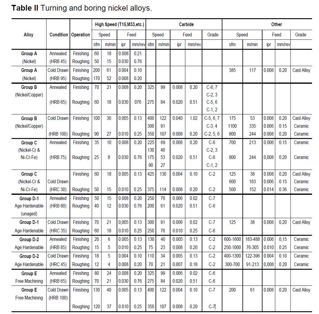
Turning, boring and grooving
Nickel Alloys can be turned with most conventional cutting materials, but the programmer / machinist should understand that productivity and economics will be highly dependant on the optimization of the machine, tool and cutting parameters.
Feed & speed suggestions for each alloy group
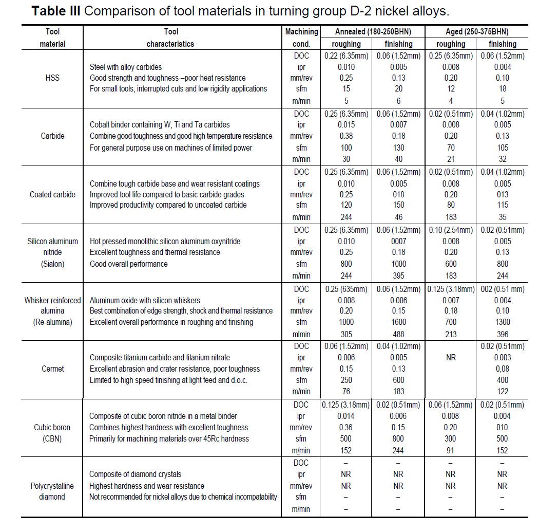
Tool materials comparison in turning for group D-2 nickel
Taking correct tool path
Taking the correct tool path is the most important actions that the programmer can take to eliminate notching. There are many techniques for doing this depending on the particular part geometry and machining operation.
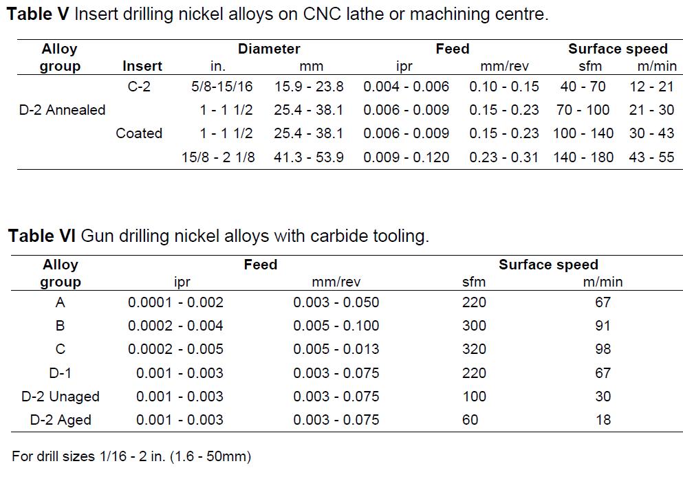
Drilling
Twist Drills
The most important consideration with twist drills is to provide positive cutting and to minimize dwell time to avoid work hardening. Satisfactory results can be obtained with conventional high sped twist drills and work hardening can be minimized if careful attention is given to the considerations known to affect twist drill performance. Set ups should be rigid and short drills or guides should be used to avoid vibration.
Inset Drills
Large diameter short holes may be drilled with insert drills on CNC Lathes and machining centres of adequate rigidity and power. A rigid set up and adequate power is essential for good performance. Tooling and inserts giving a positive rake angle are recommended to minimize cutting forces and work hardening.
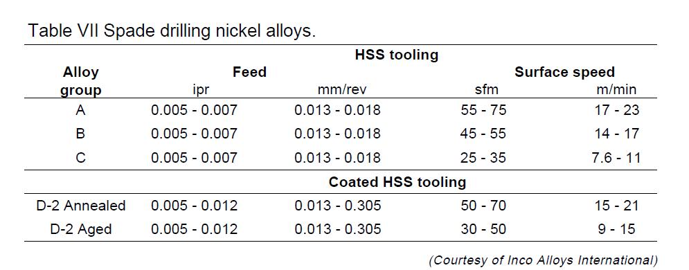
Deep Hole Drilling
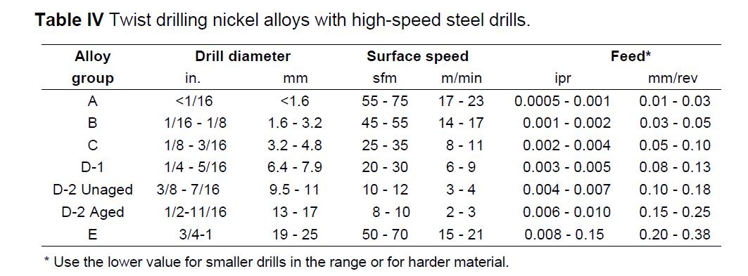
Depending on the hole diameter and depth, crankshaft, spade and gun drills are all options for deep hole drilling Nickel Alloys. Because of high strength and work hardening, the need to provide positive feed is extremely important.
Under the best of conditions drilling rates will be low as detailed in Table 4-7.
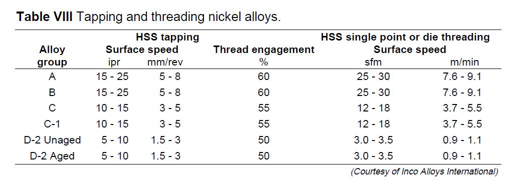
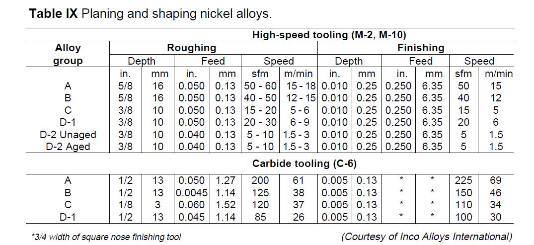
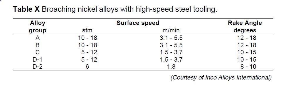
Tapping/ threading/ planning / shaping/ broaching
In tapping Nickel Alloys the most important factor is the selection of the proper hole size. Decreasing the thread engagement decreases the torque necessary to drive the tap and markedly reduces tap breakage. Conventional thread engagement values of 75% are unnecessary with high strength materials. Usual thread engagements of 50% to 60% are sufficient for most requirements. Ample lubricant preferably with liquid chlorinated wax is essential for both hand and machine tapping. The principles used in lathe threading Nickel Alloys are the same as turning.
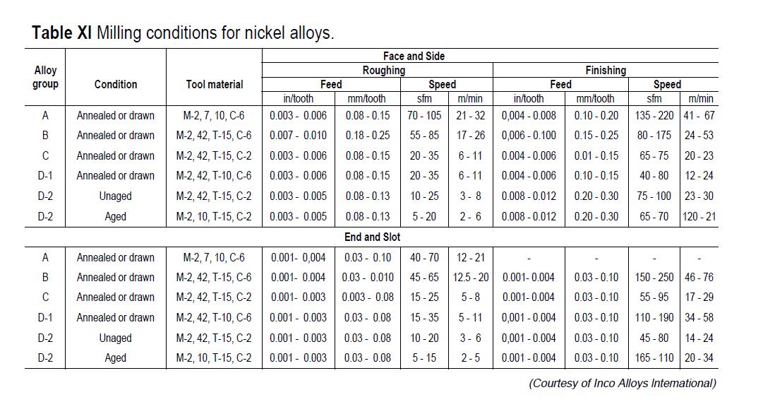
Milling: Conventional Mill Cutters
The rule that conventional milling results can be obtained through a careful balance of cuter diameter, number of teeth, feed per tooth, cutting speed and chip space applies strongly to the milling of Nickel Alloys. In addition, machine power, condition and set up that affect chatter are extremely important because of the high strength and work hardening characteristics of Nickel Alloys. Machines should have adequate power and rigidity. In general tooling should have positive cutting angles, keep sharp and light feeds should be avoided to minimize the formation of a work hardened surface layer.
Machining Titanium Alloys
Titanium alloys are used to make aircraft structural components, the component could require 90% of the material to be milled away before the part is complete.
TOP 10 TIPS
1. Keep radial engagement low
One of the crucial challenges of machining titanium is high heat dissipation. In this metal, relatively little of the heat generated during the machining operation is ejected with the chip. Compared to machining other metals, a larger percentage of the heat in a titanium machining process instead goes into the tool. Because of this effect, the choice of radial engagement dictates the choice of surface speed in this metal.
Full slotting—meaning 180-degree engagement—demands a relatively low surface speed. But reducing the radial engagement minimises the time the cutting edge generates heat, and allows more time for the cutting edge to cool before entering the material on the next rotation. Thus, as radial engagement is reduced, the surface speed can be increased while maintaining the temperature at the cut point. For finishing, a milling process consisting of a very small arc of contact with a sharp, honed cutting edge and a high surface speed and minimal feed per tooth can yield exceptional results.
2. Increase flute quantity
Commonly used end mills have four or six flutes. In titanium, this might be too few. The more effective number of flutes could be ten or more.
Increasing the number of flutes compensates for the need for a low feed per tooth. The close flute spacing of a 10-flute tool is too tight for chip clearance in many applications. However, productive milling of titanium already favours a low radial depth. The small chip resulting from this leaves open the freedom to use a high-flute-count end mill to increase productivity.
3. Make a thick-to-thin chip
Climb milling” is the familiar term for this idea; meaning do not feed the milling cutter so that the edge moves through the material in the same direction that the tool is feeding. Known as “conventional milling,” this approach to machining causes the chip to start thin and become thicker. As the tool impacts the material, friction forces create heat before the material starts to shear away from the parent metal. A thin chip is unable to absorb and eject this generated heat, which instead goes into the cutting tool. Then, at the exit point where the chip is thick, increased cutting pressure makes chip adhesion a danger.
Climb milling—or thick-to-thin chip formation—starts with the cutting edge entering the excess material and exiting on the finished surface on side milling, the tool tries to “climb over” the material, creating a thick chip on entry for maximum heat absorption and a thin chip on exit to prevent chip adhesion.
Contour surface milling demands close examination of the tool path to ensure that the tool continues to enter on the excess material and exit on the finished surface in this way. Achieving this during intricate passes is not always as simple as merely keeping the material to the right.
4. Arc in
In titanium and other metals, tool life is lost in moments of jarring change in force. The worst of these moments often occurs when the tool enters the material. Directly feeding into the stock (as almost any standard tool path would do) produces an effect similar to hitting the cutting edge with a hammer. Gliding in softly by creating a tool path that arcs the tool into the material instead of entering it in a straight line is recommended.
In thick-to-thin milling, the arc of tool path entry should follow the same direction (clockwise or counter clockwise) as the rotation of the tool. The arcing entry path allows for a gradual increase in cutting force, preventing snatching or tool instability. Heat generation and chip creation also increase gradually until the tool is fully engaged in the cut.
5. End on a chamfer
Jarring changes in force can occur at the tool exit as well. As useful as thick-to-thin cutting is the problem with this method is that the thick-to-thin formation suddenly stops as the tool reaches the end of the pass and starts to clear the metal. The abrupt change produces a similar abrupt change in force, shocking the tool and perhaps marring the part surface. To prevent the transition from being so sudden, take the precaution of first milling a 45-degree chamfer at the end of the pass so that the tool sees a gradual decline in its radial depth of cut.
6. Rely on secondary relief
A sharp cutting edge minimises cutting forces in titanium, but the cutting edge also needs to be strong enough to resist cutting pressure. A secondary-relief tool design, in which the first positive area of the cutting edge resists forces, after which the second area falls away to increase clearance, accomplishes both these objectives. Secondary relief is common in tooling, but in titanium in particular, experimenting with tools having different secondary-relief designs might reveal surprising changes in cutting performance or tool life.
7. Alter the axial depth
At the depth of cut, oxidation and chemical reaction can affect the tool. Early damage can occur at this one spot if the tool is repeatedly used at the same depth. When taking successive axial cuts, this damaged area of the tool can cause work hardening, as well as lines on the part that are unacceptable for aerospace components, meaning this effect on the surface can necessitate an early tool change. To prevent this, safeguard the tool by changing the axial depth of cut for each pass, distributing the problem area to different points along the flute.
In turning, a similar result can be achieved by taper turning the first pass and parallel turning the subsequent pass, preventing depth-of-cut notching.
8. Limit the axial depth around slender features
The ratio 8:1 is useful to remember when milling thin walls and unsupported features in titanium. To avoid deflection of pocket walls, mill these walls in successive axial stages instead of milling to the entire wall depth with one pass of an end mill. Specifically, the axial depth of cut at each step down should not be greater than 8 times the thickness of the wall that will be left behind after these milling passes are performed. If the wall is 0.1 inch thick, for example, the axial depth of cut for a milling pass adjacent to it should be no more than 0.8 inch.
Despite the depth limit, it is possible to work this rule so that productive milling is still possible. To achieve this, thin walls can be machined so that an envelope of rough stock remains around the wall, making the feature 3 or 4 times thicker than the final feature. If the wall is held to 0.3-inch thick, for example, then the 8:1 rule allows an axial depth of 2.4 inch. Following these passes, take lighter axial depths to machine the thick walls down to their final dimension.
9. Choose a tool much smaller than the pocket
Because of the extent to which the tool absorbs heat in titanium, the tool needs clearance to allow for cooling. When milling a small pocket, the diameter of the tool should be no more than 70% of the diameter (or comparable dimension) of the pocket. Smaller clearance would essentially risk insulating the tool from coolant, as well as trapping the chips that might otherwise carry at least some of the heat away.
The 70% rule can also be applied to a tool milling across the top of a surface. In this case, the width of the feature should be 70% of the tool diameter. The tool is offset 10% to encourage thick-to-thin chip creation.
10. Take a cue from tool steel
High-feed mills—a tool concept developed for machining tool steels in the die/mould industry—have been adapted in recent years to machining titanium. A high-feed mill requires a light axial depth of cut, but when run at this light depth, the tool permits feed rates higher than milling cutters with more conventional designs.
The reason is chip thinning. The key to a high-feed mill is an insert with a large-radius curve to its cutting edge. This radius spreads the chip formation across a large contact area on the edge. Because of the resulting thinning, a 0.040-inch axial depth of cut might produce a chip thickness of only about 0.008 inch. In titanium, this thin chip overcomes the low feed per tooth typically required in this metal. The thinning of the chip opens the way to a higher programmed feed rate than would otherwise be possible.
